Sinalgo - Simulator for Network Algorithms |
|
|
|
Running SinalgoWe have already seen that the toy release of Sinalgo only needs a double click to start. This section describes the more advanced possibilities to launch and configure Sinalgo.
Increase the VM MemoryWith increasing size of the networks you simulate, Sinalgo requires more memory. By default, Java provides only around 128MB. In order to increase the amount of memory Java is allowed to use, modify the configuration file of your project and set the entry javaVMmaxMem to an appropriate value (in MB).Note: Do not use the -Xmx flag for the virtual machine. This flag only affects the Run application, which starts the simulation in a separate process. The Run CommandThe Run command used to launch Sinalgo is a helper process to start the simulation process. I.e. when starting Sinalgo through java -cp binaries/bin Sinalgo.Run, the initial java process launches a second process, in which the simulation takes place. This allows the first process to read the configuration file of the selected project, set the maximum memory that may be used by the simulation process, and start the simulation process using the additional commands specified in the config file.Depending on your OS and installed applications, you may have several tools at hand that may facilitate simulations with Sinalgo. Below is a brief list of how you may edit the javaCmd field in the config file:
Command Line Configuration of SinalgoCalling Sinalgo without any arguments opens the project selection dialog. This dialog shows the available projects you may choose from, and gives you the possibility to alter the configuration of the projects. Refer to the Configuration section of the tutorial to learn more about how to configure your project.By passing on arguments on the command line (or through your IDE), you can influence the execution of Sinalgo. The following list describes the recognized command line arguments.
Example 1The following arguments open project sample1, and generate 1000 nodes of type S1Node from project sample1. The nodes are distributed according to the Random distribution model. After generating the nodes, the framework performs 10 rounds, but only draws the GUI every second round.-project sample1 -gen 1000 sample1:S1Node Random -rounds 10 -refreshRate 2 Example 2The following arguments open project sample2, and generate 10000 nodes of type S2Node from project sample2. The nodes are distributed according to the Random distribution model. Furthermore, the connectivity model is set to QUDG (which is in the default project), and the mobility model is set to LakeAvoid from project sample2.-project sample2 -gen 10000 sample2:S2Node Random C=QUDG M=sample2:LakeAvoid Note that in this case, the disambiguation is not necessary, and the following arguments result in the same behavior. -project sample2 -gen 10000 sample2:S2Node Random QUDG sample2:LakeAvoid Example 3In order to enable mobility, disable interference, and set rMax of the GeometricNodeCollection to 50 you would add the following -overwrite argument:-overwrite mobility=true interference=false GeometricNodeCollection/rMax=50 Example 4You may place several -gen arguments to generate distinct sets of nodes:-project sample1 -gen 100 sample1:S1Node Random UDG -gen 50 DummyNode Circle QUDG -gen 10 sample2:S2Node Random Thus, it is possible to use nodes and models from several projects. But note that the configuration is loaded from the selected project. True batch mode without windowsRunning Sinalgo without any windows in true batch mode may require that you start the application with the flag-Djava.awt.headless=true
If you launch Sinalgo via the Run class, you may need to specify
this flag twice: once for calling Run, and once in the project
configuration through the javaCmd property.
Running Sinalgo from ScriptsInstead of typing the basic java command for every run, you may make use of a script (batch) file that encapsulates the call to java with the necessary parameters described above. Two such scripts are included in the root directory of the regular release: sinalgo.bat for the Microsoft Windows cmd shell, and sinalgo for bash shells. Instead of typing
java -cp binaries/bin sinalgo.Run -project sample1
only write:
sinalgo -project sample1
Automating SinalgoA simulation often consists of several runs of Sinalgo, each time with slightly different parameters. The variation of the parameters is achieved easiest by using the -overwrite command line parameter, as described above. To call Sinalgo automatically several times with the distinct command line parameters, we propose to use a scripting language, the example below uses perl.
The flags -project, -gen, -rounds, and -refreshRate are presented above. The remaining parameters overwrite the default entries in the project specific configuration file. Alternatively, we could add the flag -batch to run the simulation in batch mode. For huge simulations with many nodes, this may be preferable. But if memory is not a limiting factor, the GUI may provide a good interface to supervise the simulation. Setting the refresh rate to a fairly high value, the GUI does not use a significant amount of simulation time. Note that pressing the stop button, and then continuing a simulation is perfectly OK and does not change the simulation result. Note: Project sample1 contains a more sophisticated run-script to demonstrate the possibilities of perl. Remember: Depending on your platform, you may need to adjust the class path separator. In the example above, we used the semicolon. But for instance on Linux, the separator is a colon, and yet other separators may be used on other platforms. Hint: Set the logToTimeDirectory such that log-files are not overwritten by a subsequent simulation. To collect simulation data from the different simulations, designate a log-file to which each simulation appends to. See Logging for more information. Installing perl: You may obtain a copy of perl from www.perl.org. Alternatively, install Cygwin and include the perl package. DebuggingThe Run class launches Sinalgo in a separate process. This has immediate consequences for running a debugger, as the simulation itself does not run in launched application. In order to use the debugger of your IDE to analyze the implemented algorithms, you probably need to do one of the steps below.a) Start Sinalgo directly using the following slightly modified command line.
java -Xmx800m -cp binaries/bin sinalgo.runtime.Main
This launches the simulation process directly, but does not allow to specify the maximum memory to be used through the config file. The -Xmx800m flag indicates that the JVM may use at most 800 MB of memory, adjust the value to your needs. b) Use remote debugging: Some java debuggers can be attached to a remote process (even running on a different machine). Remote debugging requires two steps. b.1) First, modify the run command for the simulation process s.t. it can communicate with the debugger. I.e. set the javaCmd entry of the config file to java -agentlib:jdwp=transport=dt_socket,address=localhost:8000,suspend=n,server=y This configures the JVM to receive connections. You are free to choose any (unused) port number in the address-flag. b.2) After starting the simulation, launch the debugger and attach it to the application. In Eclipse, call Run -> Debug... and create a new configuration for a Remote Java Application. Select the Connection Type to be Standard (Socket Attach), and the Connection Properties to match the address specified in the javaCmd. Hot Code ReplaceThe exchange of class files at runtime is called 'hot code replace' and can be performed by most IDEs, e.g. Eclipse. For that purpose, your IDE transfers the new class files over the debugging channel to the JVM running Sinalgo. Therefore, hot code replace requires Sinalgo to run in debugging mode.Note: Hot code replace is only possible if the signature of the replaced class files remains the same. I.e. you may change the body of a method, but not the signature of the method. It is neither possible to add/remove methods or global variables. GUI DescriptionThis section summarizes the methods and helper-functions provided through the GUI of Sinalgo.MenusThe Graph menu provides the following tasks:
The Global menu contains all global custom methods and the Settings dialog, which displays a list of all settings. GUI Interaction
|
||||||||||||||||||||||||||||||||||||||||||||||||||||||||
© Distributed Computing Group 

|


 button. In
synchronous simulation mode, this executes the number of rounds
specified in the Rounds to Perform text field. In asynchronous
simulation mode, this executes the number of events specified in the
Events to Perform text field.
button. In
synchronous simulation mode, this executes the number of rounds
specified in the Rounds to Perform text field. In asynchronous
simulation mode, this executes the number of events specified in the
Events to Perform text field.
 button. After pressing the button, the simulation will finish the
currently executing round/event before it stops. Thus, this button is
only useful if you set the Rounds to Perform or Events to
Perform field to a value above 1.
button. After pressing the button, the simulation will finish the
currently executing round/event before it stops. Thus, this button is
only useful if you set the Rounds to Perform or Events to
Perform field to a value above 1.

 .
.
 button to set the
zoom factor such that the simulation area just fits on the screen.
button to set the
zoom factor such that the simulation area just fits on the screen.
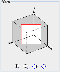
 button to reset the default view of the cube.